Thermo Guide #
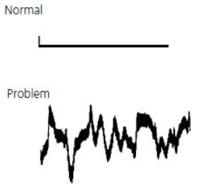
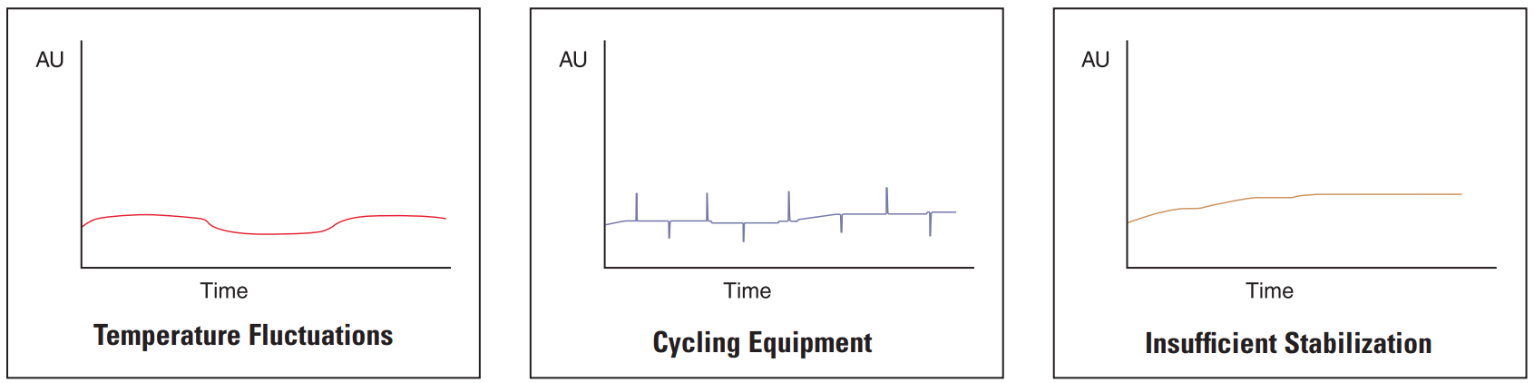
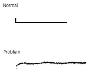
Baseline irregularities can be non-cyclic (erratic) or cyclic (follow a pattern). They can originate from:
- electrical interferences,
- detector faults,
- solvent impurities,
- column contamination etc.
To isolate the source of a baseline irregularity, it is important to determine whether the problem lies with the fluid path, detector or electrical connections. This can be achieved by following the simple steps below:
-
Turn off the instrument pump – fluid flow must be zero
-
Monitor the baseline for 5 to 10 minutes. Note if there is any improvement in the baseline’s appearance. If yes, then the problem lies within the instrument fluid path. If no, the problem is either electrical or detector related.
-
Disconnect the detector electrical cables from the A/D interface with the PC, integrator and chart recorder, i.e. the data handling devices. Attach a jump source to the input terminals on the data- handling device (a crocodile clip, paper clip etc). If the noise ceases, then the problem is within the detector or it’s electrical connections. If the noise continues, then the problem is within the data-handling device.
Data-handling device troubleshooting is beyond the scope of this guide.We recommend that you contact your instrument provider for this service.
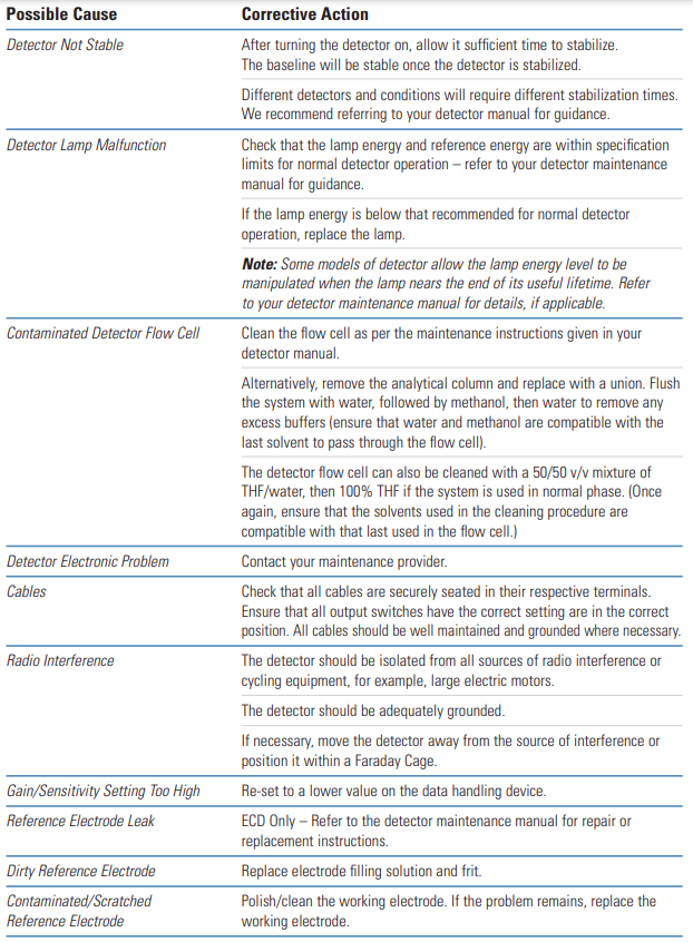
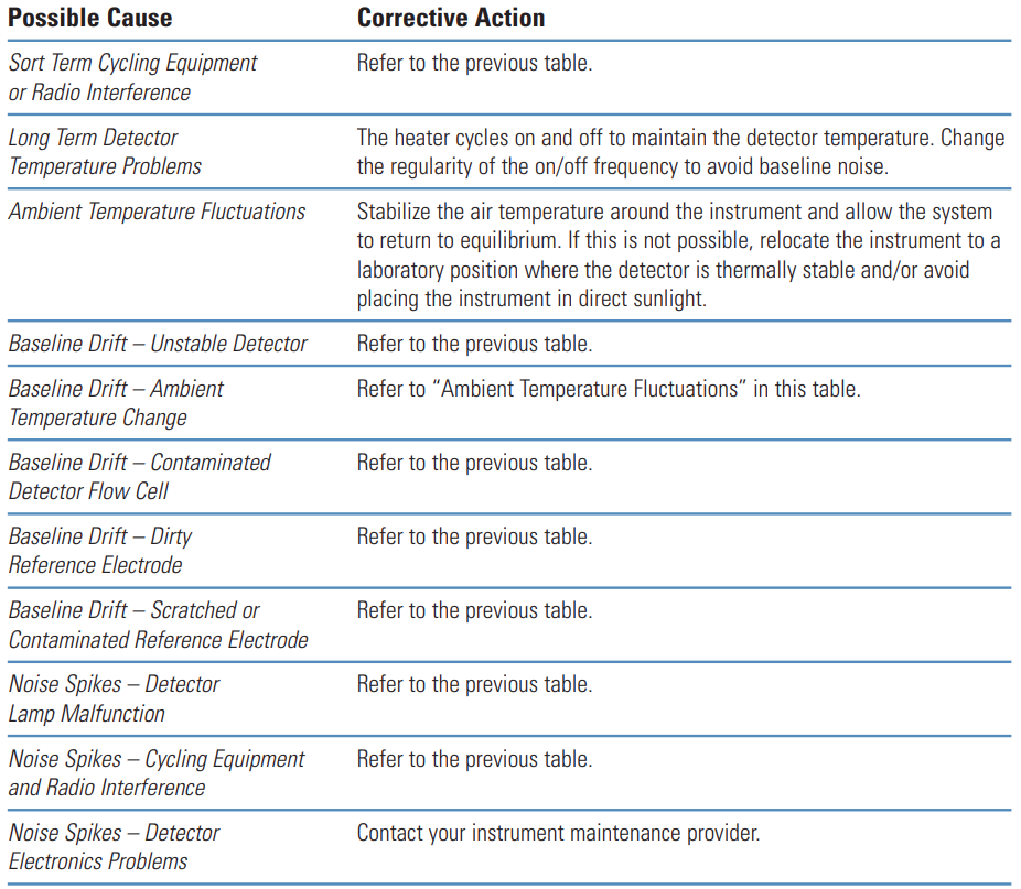
The sections provide a quick reference guide for typical baseline irregularities, their causes and corrective action that can be taken to cure the problem.
Non-Cyclic Noise – Fluid Path Problems #
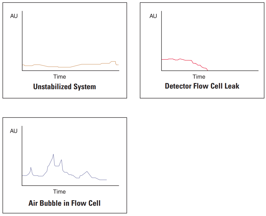
The most common cause of non-cyclic baseline noise related problems is air in the system. To overcome this, all solvents should be thoroughly degassed prior to use, all lines should be purged with solvent and the pump should be thoroughly primed.
Air bubbles can obscure the detector flow cell and cause baseline noise – be aware that from time to time, the cell may require cleaning and/or removal of air bubbles.
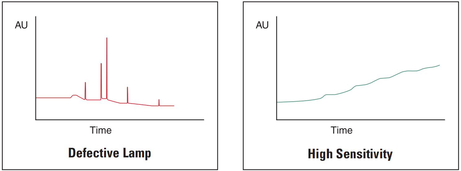
Non-Cyclic Noise – Detector Electronics Problems #
Note: This section is based on HPLC with DAD detector.
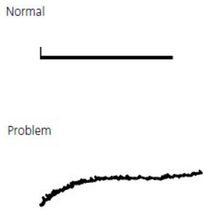
The most common cause of problems related to electronic baseline noise is the detector. Usually, if the detector is allowed insufficient time to equilibrate before an injection is performed, then the resultant chromatogram will contain spurious peaks and there will also be some evidence of baseline drift.
If the problem occurs after routine maintenance, check that all the cables are securely seated in their sockets and that the correct cable is in the correct socket. Also check that all settings have been returned to their positions prior to the routine maintenance.
Cyclic Noise – Detector Related Problems and Others #
The most common cause of cyclic baseline noise is the detector. Usually, if the detector is allowed insufficient time to equilibrate before an injection is performed, then the resultant chromatogram will contain spurious peaks and there will also be some evidence of baseline drift.
Sigma-Aldrich Guide #
Problem | Probable Cause | Remedy/Comments |
|---|---|---|
|
1. Column temperature fluctuation. (Even small changes cause cyclic baseline rise and fall. Most often affects refractive index and conductivity detectors, UV detectors at high sensitivity or in indirect photometric mode.) |
1. Control column and mobile phase temperature, use heat exchanger before detector. |
Problem | Probable Cause | Remedy/Comments |
|---|---|---|
|
1. Air in mobile phase, detector cell, or pump. |
1. Degas mobile phase. Flush system to remove air from detector cell or pump. |
Problem | Probable Cause | Remedy/Comments |
|---|---|---|
|
1. Leak. |
Check system for loose fittings. Check pump for leaks, salt buildup, unusual noises. Change pump seals if necessary. |