The purpose of a well-plumbed HPLC system is to minimize dead volume between it’s components and to eliminate leaks.
System tubing errors show themselves in many ways, for example as band broadening, baseline noise, etc. Detection of incorrect diameter tubing is often very difficult once it is in-situ. For this reason, we recommend that all plumbing changes be recorded in the instrument maintenance log. It is easier then to pinpoint the most recent changes. An example of an instrument maintenance log is shown in Appendix C of this guide.
The internal diameter of tubing used in a HPLC system varies with the position in the instrument. Refer to your system maintenance manuals to determine the recommended tubing for a specific application.
Note: Most suppliers of HPLC tubing now color code their products for ease of internal diameter identification.
The type of tubing used is determined by the application that is being performed. The two most common types of tubing are stainless steel and PEEK™, although others are also available. When changing tubing, make sure that the replacement is manufactured from a material that is compatible with any solvents that may be flushed through it.
Thermo Guide #
Cutting tubing #
Stainless Steel #
Stainless steel can be effectively cut using the procedure outlined below:
-
Estimate the length required. Remember to allow extra length if the tubing is to go around corners as sharp bends in the tubing will distort the inside bore and hence the solvent flow through it.
-
Using a stainless steel cutter, score cleanly round the tubing. If a cutter is unavailable, use a knife-file to score the tubing. Care should be taken, whichever method is used, not to distort or damage the tubing.
-
Using two pairs of smooth jawed pliers, one above the score and one below it, gently bend the tubing back and forth until it snaps. Excessive bending should be avoided as this will damage the tubing and not give a clean break.
-
There will be one or two burrs present on the cut surface. These can be carefully filed away to give a smooth, flat cut surface. Care should be taken not to allow any filed material to block the tubing bore.
PEEK or Polymeric Tubing #
The simplest way to cut polymeric tubing is using a blade, for example a razor blade or craft knife. The polymeric tubing cutters that are supplied by many manufacturers are essentially a razor blade in a safety housing. The advantage of using one of these cutters is that they hold the tubing at 90° to the blade so a clean, flat cut is assured.
Polymeric tubing can be effectively cut using the procedure outlined below:
-
Estimate the length required. Remember to allow extra length if the tubing is to go around corners as sharp bends in the tubing will distort the inside bore and hence the solvent flow through it.
-
Use a sharp blade or specialist cutter to cut the tubing. Do not use a “sawing” action. This will give an uneven cut surface. Make the cut in a single action.
-
Inspect the cut surface for burrs. These can be carefully filed away to give a smooth, flat cut surface. Care should be taken not to allow any filed material to block the tubing bore.
As a final action, after cutting the tubing and before connecting it to the HPLC, flush it with solvent to remove any filed material, dust or other debris that could be in the tubing bore. The tubing is now ready to have fittings attached to it.
Fittings #
Fittings are available in stainless steel and a range of polymeric compounds. In general, you should use stainless steel fittings with stainless steel tubing, PEEK fittings with PEEK tubing etc.
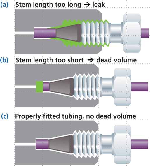
We recommend that compression fittings and ferrules from different manufacturers are never interchanged. The dimensions of the fitting and ferrule vary between suppliers, so mixing them often leads to leaks, stripped threads and damage to female ports such as column inlet and outlets, detector inlets etc.
The amount of tubing that extends past the ferrule also varies with manufacturer. If the tubing does not seat properly within the female fitting, then leaks and increases in dead volume will occur.
Laboratories that contain instruments from more than one manufacturer often find it useful to purchase “universal” fittings. These fittings are compatible with all instruments.
Credit: Optimizing HPLC and UHPLC Performance with Agilent A-line Quick Connect Fittings
Note: Care should always be taken when tightening fittings. Over-tightening can cause damage to the fitting threads, ferrules etc, causing the unit to leak, or in worse case scenarios, causing the fitting to break off in the housing.
The use of fingertight fittings is recommended wherever possible. These require no additional tools to form a leak-proof seal.
Block tubing #
Blocked tubing can either be replaced or the blockage removed. If no replacement tubing is readily available, the blockage can be done in the following way:
-
Isolate the blockage, as described in section 3.2.1 of this guide.
-
Remove the piece of tubing from the instrument, reverse it and attach the reversed end directly to a pump.
-
Flush the tubing at approximately 0.5 mL/min with a suitable solvent to remove the blockage. If the material blocking the tubing is not known, use a 50% aqueous methanol solution.
-
There are occasions when this flush procedure will not remove the blockage, for example if it is due to a large insoluble piece of seal etc. In such circumstances, increase the flow rate to between 3 and 5 mL/min to force the blockage out. This flush should be used as a last resort because of the risk of formation of solvent aerosols as the tubing unblocks. If this flush is used, ensure that the waste end of the tubing is placed in a covered beaker or sealed waste bottle for safety.
-
If the tubing remains blocks after flushing, then it must be replaced.
Old and Leaking Fittings #
Compression and finger tight fittings have a finite lifetime. Eventually, they will have to be replaced with new ones. The ferrule of the worn fitting will be swaged to the tubing; i.e. it will be irremovable (stainless steel) or will be removable but will leave an indentation around the tubing (PEEK). This section of tubing cannot be used again as it would not seal properly and would leak.
To change a fitting, follow the guideline below:
Compression Fitting
-
Turn off all pumps – solvent should not be flowing through the system.
-
Remove the fitting from it’s housing.
-
Cut the tubing between the ferrule and fitting. If this is not possible, cut the tubing before the fitting.
-
Ensure the tubing’s cut end is flat and burr free. Inspect the old fitting; if it is worn, replace it. If it is not worn, it can be re-used with a new compatible ferrule. Note: Leaking fittings are often caused by damaged, mis-shapen ferrules, so it is not necessary to replace the whole fitting if only a part of it is damaged.
-
Assemble the new fitting and ferrule on the tubing and tighten into it’s housing to swage the ferrule onto the tubing. If the fitting still leaks after this, replace the tubing.
Fingertight Fitting
- Turn off all pumps – solvent should not be flowing through the system.
- Remove the fitting from it’s housing.
- Slip the fitting and ferrule (if it has a separate one) from the tubing.
- Inspect the tubing for defects. Remove the end of the tubing if necessary.
- Place the new fitting on the tubing and tighten it into it’s housing. If the fitting still leaks after this, replace the tubing.
SLIPFREE Fitting
- Turn off all pumps – solvent should not be flowing through the system.
- Remove the fitting from it’s housing.
- Check the ferrule for damage – this is the most likely cause of leaks. The SLIPFREE ferrules do not swage onto the unit’s tubing, unlike other ferrules, so they can easily be replaced.
- Replace the ferrule and reassemble the SLIPFREE connector into it’s housing. If the fitting still leaks, replace the entire SLIPFREE unit.
Important: There are occasions where the fitting or ferrule is not the cause of solvent leaks. They can be generated by degeneration of the fitting housing. Where persistent leaks occur, even after fitting changes, it is worth while inspecting the housing for damaged threads, blockage etc.
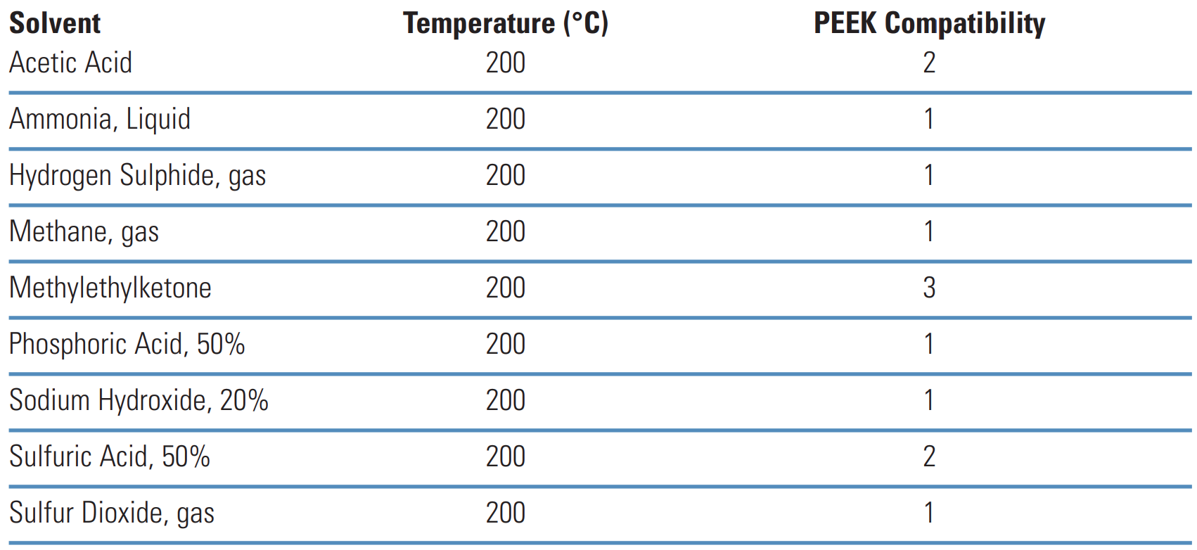
Chemical Compatibility of Polymeric Tubing with Solvents #

Note:
1 = Compatible, no adverse effect.
2 = Application dependant.
3 = Not compatible/recommended. No figure denotes compatibility not calculate
Note:
1 = Compatible, no adverse effect.
2 = Application dependant.
3 = Not compatible/recommended. No figure denotes compatibility not calculated.
LCGC Dwight R. Stoll Guide Combined with an Agilent Webinar and a Thermo Poster #
Reviewing the Basics #
What follows is a short list of the characteristics of an ideal connection between components of an LC system:
- Leak-free (today, up to 20,000 psi, or more)
- No unswept volumes (also referred to as voids or dead volumes)
- No distortion of connected parts
- The connection can be broken and remade (that is, disconnected and reconnected) many times without changes in performance
- Inexpensive components
As with most things in chromatography we end up making compromises, and so it is too with fittings and connections in LC that we cannot have everything we want. I think the adage “you get what you pay for” mostly applies here in the sense that we have to pay more for fittings that consistently provide good performance and convenience. Figure 6 shows the anatomy of a typical connection in an LC system. This connection could be between a valve port or column endfitting and a connecting capillary, for example. The vast majority of consumables on the market for this purpose rely on the formation of a seal between the cone-shaped ferrule and the cone-shaped part of the receiving port. The nut drives this ferrule into the port, making leak-tight contact between the two surfaces (metal–metal, metal–polymer, or polymer–polymer). At the same time, the compression of the cone on the ferrule occurs with enough force that the ferrule effectively becomes locked into place, especially for metal ferrules.
Credit: Optimizing HPLC and UHPLC Performance with Agilent A-line Quick Connect Fittings
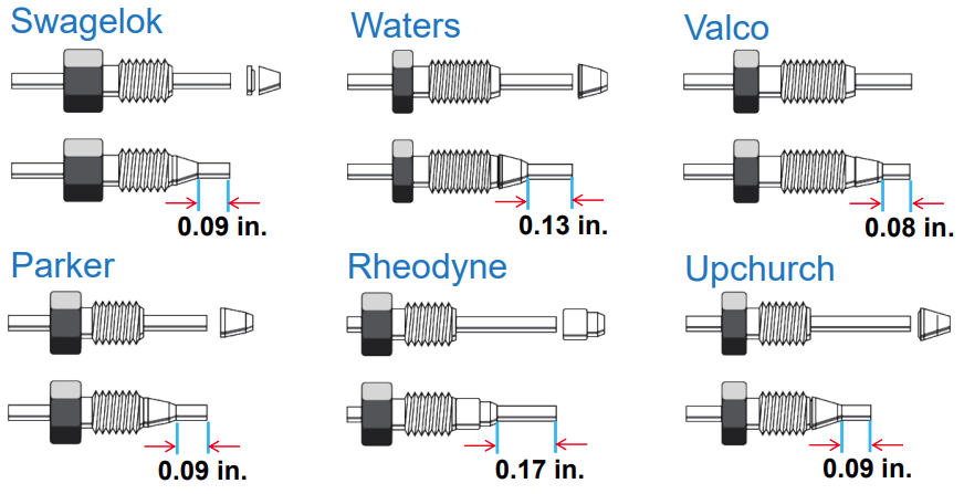
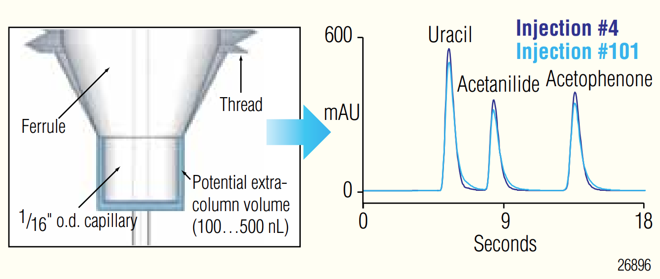
Figures 6a and 6b show the two most common ways that this connection process can go wrong. In the first case, if anything prevents the ferrule from moving fully into the receiving port, there is insufficient contact between the ferrule and the port surface, and the connection will leak, anywhere from a little to a lot. This situation most commonly results from using a connecting capillary that has the ferrule preswaged (that is, locked into place as a result of a connection made previously with a different receiving port) to a port depth that is different from the port depth involved in the current connection.
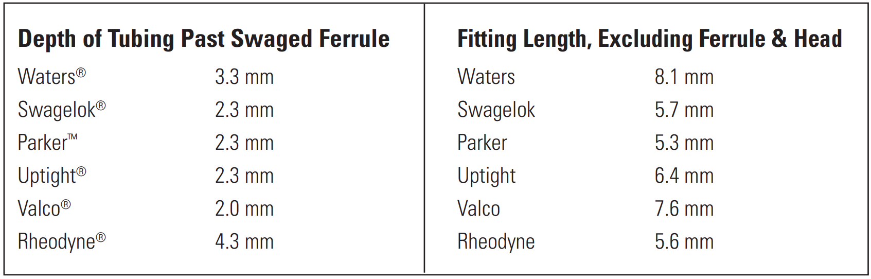
Figure 7 shows that port depths vary by manufacturer, with differences ranging from zero to several millimeters. In the second case (Figure 6b) the ferrule is positioned too close to the end of the capillary, this time resulting in an unwanted void volume in the port. This incorrect positioning and added void volume can result again from moving a capillary with a preswaged ferrule from one port to another, or even from breaking and remaking a connection to the same port. The unwanted additional volume inevitably causes broadening of peaks observed at the detector; whether or not it results in a measurable increase in peak width or change in peak shape will depend on a number of factors including the size of the void, the inherent performance of the column (that is, how narrow the peaks are in volume units), and conditions of the experiment. This effect usually appears as additional peak tailing, and will be most pronounced for early-eluted peaks.
Credit: Optimizing HPLC and UHPLC Performance with Agilent A-line Quick Connect Fittings
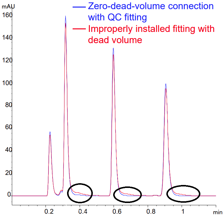
Figure 8 shows an example of this effect, where a very long tail was observed in the case when a small void was deliberately introduced in the column connection by using an improperly positioned ferrule. The type of tailing observed in this instance can be very problematic in cases where a small peak of interest is eluted in the tail of a much larger neighboring peak, and the chromatographic resolution is compromised because of the bad connection. Below is an instruction video on Youtube.
Credit: Optimizing HPLC and UHPLC Performance with Agilent A-line Quick Connect Fittings
Some Things Stay the Same, But . . . #
The basic principles associated with good connections in LC have not changed since the days of the early high performance liquid chromatography (HPLC) systems. Indeed, the images shown in Figures 6 and 7 are very similar to the ones used by John Dolan and his coauthors in the early “LC Troubleshooting” columns he wrote in the 1980s on this topic$^{1,2}$. However, I’d like to comment specifically here on three aspects that have changed quite a bit since then.
Cutting Your Own Tubing #
In his 1984 article (1), Dolan encouraged purchasing precut tubing, but gave advice for making good cuts in the case when you need to cut your own tubing. There was a time when I cut my own metal tubing too, but in hindsight those capillaries were awful. Given the relatively low cost of precut metal tubing today, and the potential for serious peak dispersion that could be introduced by a bad cut, it is hard to imagine justifying cutting our own tubing now. Plastic tubing, typically made of PEEK for high-pressure connections up to about 5000 psi, is a different story, however. In this case, it is relatively easy to make a good, clean, and square cut using a cutter designed for this purpose, which is available from most consumable vendors. In my laboratory, we use a lot of PEEK tubing, especially in situations where we are experimenting with different instrument configurations. After we settle on a configuration we like, then we will change all of the connections to metal capillaries because we find them to be the most reliable over time.
Interchangeability of Fittings and Multiple Connections #
In a 1988 article (2), Dolan argued that the specific ferrule type did not matter much, as long as the tubing stem depth (see Figure #) is matched to the receiving port, because the shape of the ferrule conforms to the shape of the port anyway. However, I think the bigger issue in practice is that this idea of interchangeability can quickly lead one to believe that a capillary with a swaged fitting can be moved from one port to another (for example, from a valve to a column, or from one column to another) without any problems. Today, I think moving these capillaries with preswaged fittings around is just asking for trouble. Disconnecting a capillary from a valve port and reconnecting it to the same port may work for a few times, but eventually this practice will lead to small leaks, and so it must be monitored carefully. Given the demands of modern columns for good connections to realize the full performance potential of the column, moving a preswaged capillary from one column to the next is more likely to be problematic than not. A systematic study of this issue by Stankovich, Guiochon, and coworkers clearly showed how serious this problem can be $^3$. They found that reusing the same preswaged fitting to connect to columns from three different manufacturers with similar endfitting designs introduced extra peak dispersion up to 7 µL$^3$! Considering that this level of band spreading happens in the column itself in some cases, this problem with the fitting could lead to efficiency losses on the order of 50% or more. The most effective way to avoid these problems is to simply use a new capillary when making a new connection, so that the ferrule is freshly swaged and adapted to the particular receiving port involved. Of course, this approach can become expensive when making many changes to a system. In my laboratory, we carefully check for leaks when remaking connections to valves and pumps using preswaged fittings. When connecting to columns, we never use the swaged fittings shown in Figure 7; instead, we use the newer types of fittings (discussed in detail below) that are designed to be reused while making good connections each time.
Fingertight Fittings #
So-called fingertight fittings are very attractive to LC practitioners simply because it is convenient to quickly make a new connection to a column or other instrument component without wrenches. Many consumables vendors advertise fingertight fittings that are leak tight up to pressures on the order of 20,000 psi without wrenches. In my laboratory, we find that some of the newer two-piece fingertight fitting designs are an improvement over older one-piece designs and are reliable up to about 10,000 psi without wrenches. Again, with this convenience comes increased costs. For very high-pressure operations up to 20,000 psi, we still find that connections are done most reliably by completing them with wrenches.
Recent Trends in Connection Technology #
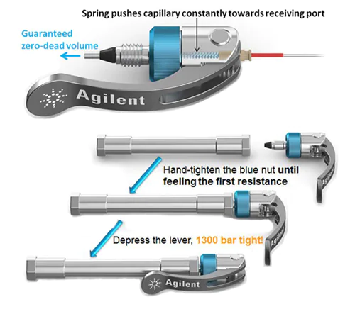
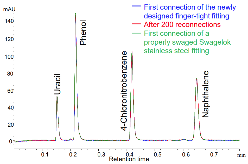
Two decades ago when the norm in column technology involved 5-µm particles in 150 mm × 4.6 mm columns, the column itself contributed a lot of the band spreading apparent in an observed peak, and thus the separations were relatively forgiving with respect to connections made between the components of the LC system. As column technology has improved, however, manufacturers have recognized the need to make good connections reliably, at high pressure, and repeatedly with the same capillary and endfitting. Two completely different endfitting designs that have been introduced relatively recently to address this need: the Quick Connect fitting (Agilent Technologies) and the Viper fitting (Thermo Fisher Scientific). In the first case, the fitting has an internal spring-based mechanism that ensures that the capillary stem is forced to the bottom of the receiving port as the fitting is tightened. This mechanism increases the likelihood of making a good connection every time by avoiding the type of void shown in Figure 1b. The fitting’s polymer-based ferrule also conforms to slight changes in receiving port shape, allowing for reuse of the fitting many times without leaks.
The chromatograms shown in Figure 11 show that this new design can provide the same high-quality connection to the column that we expect from the swaged metal ferrule design, as we do not observe the severe peak tailing resulting from a bad connection as shown in Figure 3. Furthermore, the chromatograms show that this high-quality connection can be made many times over using the same fitting without any performance losses.
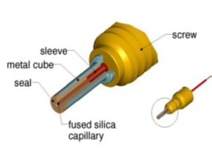
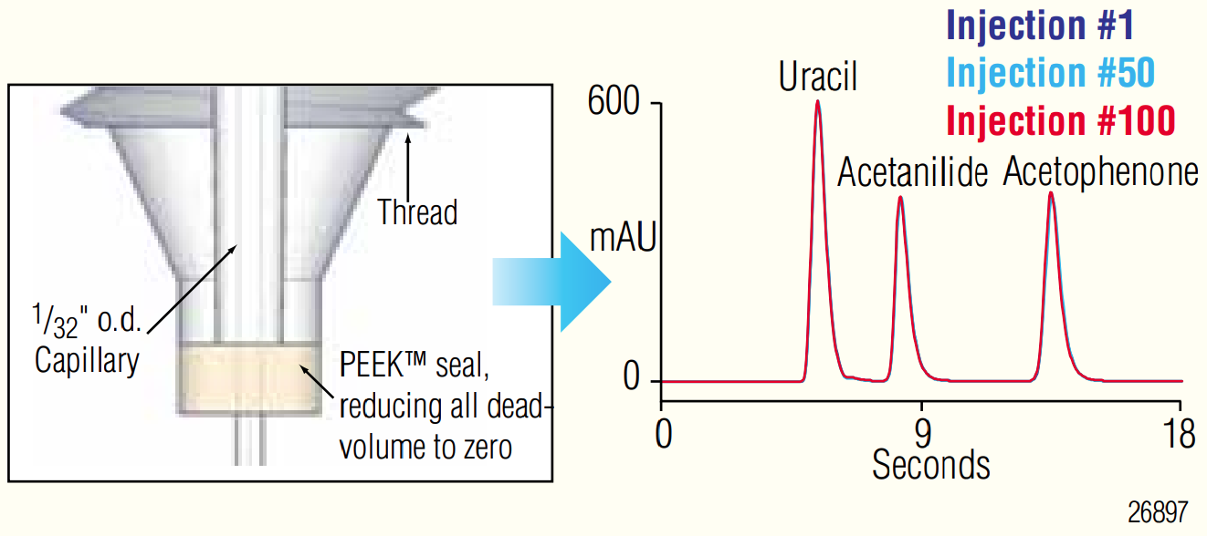
Finally, Figure 13 shows the design of a fitting based on an approach that is completely different from the cone-shaped ferrules that have been used historically. In this case, the seal between the capillary and the receiving port is made at the very bottom of the port, increasing the likelihood that a void-free connection will be made. As with the previous design, the sealing component is polymeric, which enables the reuse of the fitting many times without performance losses. Here again these performance advantages and conveniences come at the cost of the price of the consumable part.
Credit: Ensuring Best Possible UHPLC Performance Through an Innovative Capillary and Fitting Design
Credit: Ensuring Best Possible UHPLC Performance Through an Innovative Capillary and Fitting Design
Summary #
LC practitioners are faced with an overwhelming number of choices for fittings that can be used to connect the components of LC systems. Users must ultimately decide which fitting technology offers the best compromise of performance and cost for each particular situation. For dedicated LC systems where system reconfiguration is infrequent-and especially for connections between instrument components excluding the column- traditional metal, ferrule-based fittings usually offer the best compromise of cost, reliability, and quality of connections. For connections to columns, particularly when changing columns frequently, reusable fittings that do not involve swaging of a metal ferrule to the capillary are very convenient. Technologies introduced by several manufacturers over the past few years have improved the design of these reusable fittings, and now enable repeated connections of high quality and at very high pressures using a single fitting. These technologies come at increased costs, but the performance gains and ease of use they provide will outweigh the costs in many practical situations.
-
J.W. Dolan and V.N. Berry, LC Magazine 2, 20–21 (1984).
-
J.W. Dolan and P. Upchurch, LC Magazine 6, 788–790 (1988).
-
J.J. Stankovich, F. Gritti, P.G. Stevenson, and G. Guiochon, The impact of column connection on band broadening in very high pressure liquid chromatography, J. Sep. Sci. 36, 2709–2717 (2013). doi:10.1002/jssc.201300175.
